
Why convert an ER diagram to tables?
An ER diagram is a design. It describes, at a high level, the "things" in your system and how they relate. A relational database, however, stores everything as tables made of rows and columns. So before you can actually build the database, you have to translate the diagram into a relational schema — a set of tables with primary keys and foreign keys. This translation is called reducing (or converting) an ER diagram to tables, and it follows a small, predictable set of rules. Learn the rules once and you can convert any diagram mechanically.
The big picture: what maps to what
Before the detailed rules, it helps to see the overall correspondence. Every shape in an ER diagram turns into a specific part of a relational schema. An entity set becomes a table. Each simple attribute becomes a column. The key attribute becomes the table's primary key. A relationship set becomes either its own table or just a foreign key, depending on the cardinality — that last case is where most of the rules live.

- Entity set becomes a table.
- Attribute becomes a column.
- Key attribute becomes the primary key.
- Relationship set becomes a table or a foreign key, depending on the cardinality.
- Entity set becomes a table.
- Attribute becomes a column.
- Key attribute becomes the primary key.
- Relationship set becomes a separate table, or a foreign key inside an existing table.
Rule 1 — Strong entity set with simple attributes
This is the simplest case. A strong entity set that has only simple attributes needs exactly one table in the relational model. The columns of the table are the attributes of the entity set, and the key attribute becomes the primary key. Nothing is split and nothing is added.
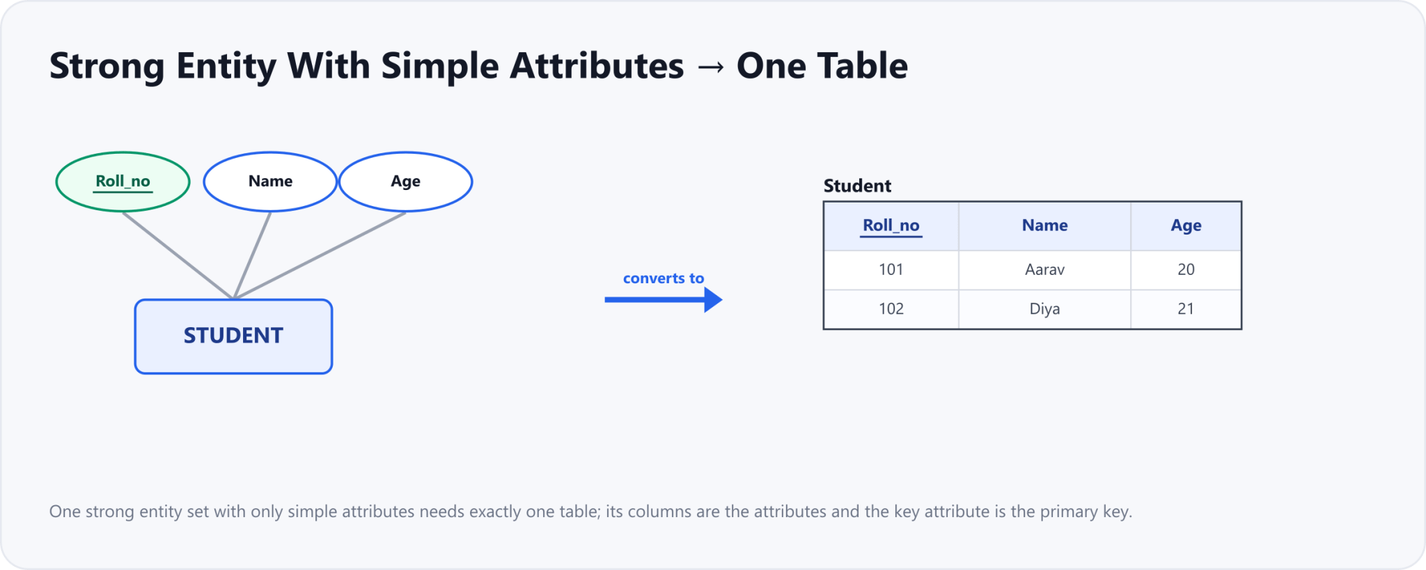
- One table is enough. The columns are the attributes: Roll_no, Name, Age.
- The key attribute Roll_no becomes the primary key of the table.
In the example, the Student entity set has three simple attributes: Roll_no, Name, and Age. It converts into a single table named Student with those three columns. Because Roll_no is the key attribute (no two students share it), it becomes the primary key — shown underlined in the table header.
Rule 2 — Strong entity set with composite attributes
A strong entity set with any number of composite attributes still needs only one table. The trick is in how the composite attribute is handled: you do not create a column for the composite attribute itself. Instead, you create a column for each of its simple (leaf) parts. The composite "parent" exists only in the diagram to group its parts; it is never stored.

- Still only one table.
- Use the simple leaf parts of the composite attribute as columns.
- Name becomes First_name and Last_name; there is no Name column.
- Final columns: Roll_no, First_name, Last_name, Age.
Here, Name is a composite attribute made of First_name and Last_name. The Student table therefore has columns Roll_no, First_name, Last_name, and Age — there is no column called "Name". If an attribute has several levels (for example, Address breaking into Street, City, State, and Country), you keep drilling down and use only the lowest-level simple attributes as columns.
Rule 3 — Strong entity set with multi-valued attributes
A multi-valued attribute breaks the "one value per cell" idea, so it cannot sit in the main table. A strong entity set with a multi-valued attribute needs two tables. The first table holds all the simple attributes plus the primary key. The second table holds the primary key together with the multi-valued attribute, and the primary key of that second table is the combination of both columns.

- Table 1 Student: Roll_no as primary key and Name.
- Table 2 Student_Phone: Roll_no and Mobile_no, both together as the primary key.
Student has a multi-valued attribute Mobile_no because a student can have several phone numbers. The first table, Student, keeps Roll_no (primary key) and Name. The second table, Student_Phone, stores one row per phone number: Roll_no plus Mobile_no. Their combination is the primary key, so the same student can appear in several rows with different numbers while each row stays unique. This also keeps every cell holding a single, atomic value — the requirement behind first normal form.
Rule 4 — Converting relationship sets
A relationship set connects entities, so to represent it you need the primary keys of the entities it connects, plus any descriptive attributes the relationship itself carries. In the most general case a relationship set becomes its own table containing those keys. But you do not always need a separate table — the cardinality ratio of the relationship decides whether the relationship earns its own table or can be folded into an entity's table as a foreign key. The next three cases work through the ratios.
Many-to-many (m:n)
When both sides are "many", neither entity can store the link on its own, so a many-to-many relationship always needs its own table. That gives three tables in total: one for each entity set and one for the relationship. The relationship table holds the primary keys of both entity sets, and its primary key is the combination of the two. Any descriptive attribute of the relationship (such as a grade or a date) also goes into this table.
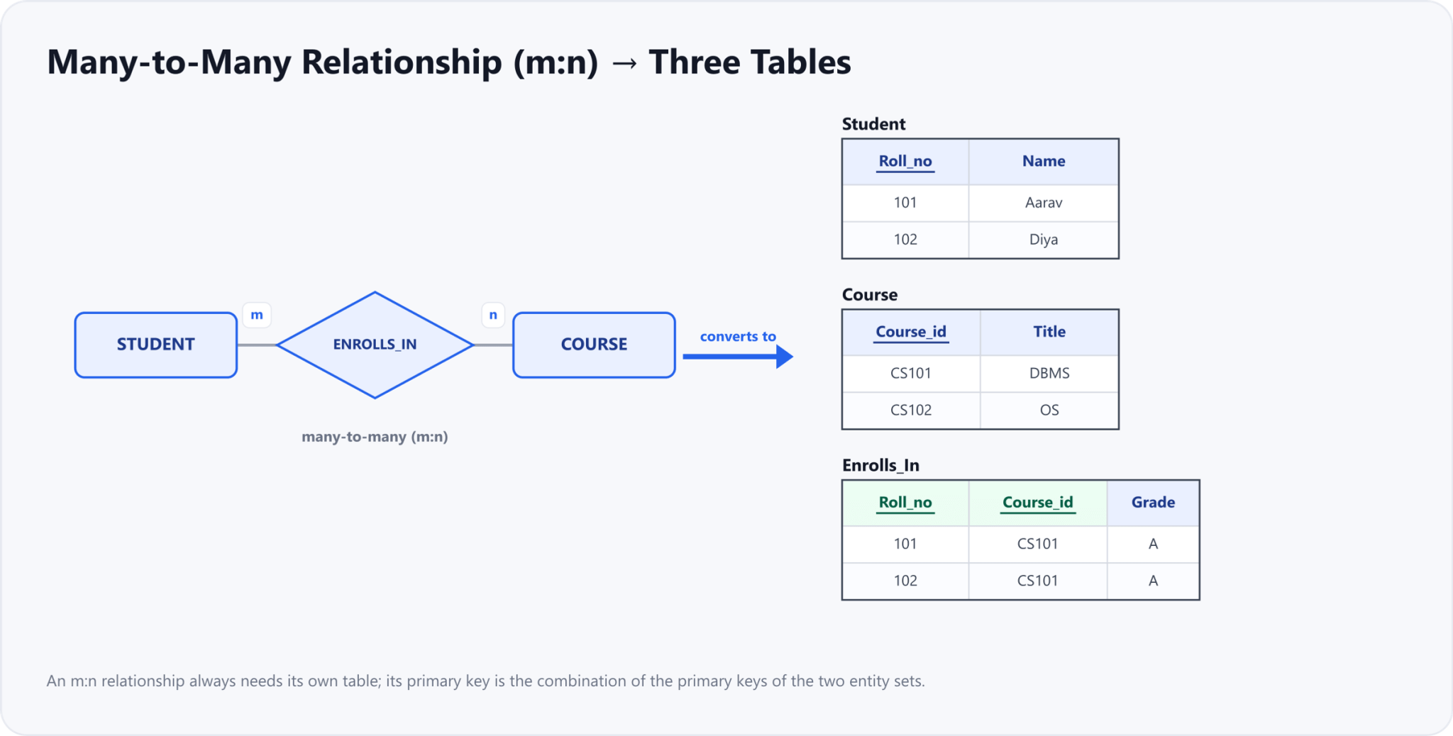
- Three tables: Student, Course, and a separate Enrolls_In table.
- Enrolls_In holds Roll_no and Course_id plus any descriptive attributes.
- Its primary key is Roll_no and Course_id together.
One-to-many (1:n) and many-to-one (m:1)
When one side is "one" and the other is "many", you do not need a third table. Each entity on the many side links to at most one entity on the one side, so you can store that single link right inside the many-side table as a foreign key. That gives two tables. A one-to-many and a many-to-one relationship are mirror images of each other — in both, the relationship merges into the entity on the "many" side.
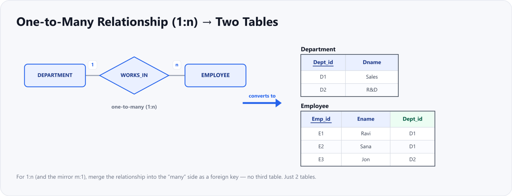
- Two tables: Department and Employee.
- Merge the relationship into the many side, Employee.
- Employee gets Dept_id as a foreign key. The mirror case M to 1 works the same way.
One-to-one (1:1)
A one-to-one relationship also needs just two tables. Because each entity on either side links to at most one entity on the other, you can place a foreign key on either side — whichever is more convenient. There is no separate relationship table. (As the next rule shows, if the participation is total on both sides, a 1:1 relationship can even collapse into a single combined table.)

- Two tables: Employee and Department.
- Put the other table key as a foreign key on either side.
- If both sides have total participation, the two tables collapse into one.
Rule 5 — Cardinality with participation constraints
Cardinality tells you how many times an entity may take part in a relationship; participation tells you whether it must take part at all. When you add participation constraints to the picture, you can sometimes reduce the number of tables further and make foreign keys safer.
Total participation on one side
Suppose one side of the relationship has total participation — every entity on that side must take part. Then you can merge the relationship into that side's table, and its foreign key can be declared NOT NULL, because every row is guaranteed to have a matching entity on the other side. The number of tables stays the same as the plain cardinality case (two tables for a 1:1 or 1:n), but the schema is tighter and the foreign key can never be empty.
Total participation on both sides
When a one-to-one relationship has total participation on both sides, every entity on each side must be paired with exactly one entity on the other. The two entity sets are effectively in lock-step, so both of them and the relationship can be folded into a single combined table — just one table in total. This is the one case where a binary relationship reduces below two tables.

- Total participation on one side: merge into that side; its foreign key is NOT NULL, still two tables.
- Total participation on both sides with a one to one ratio: fold everything into a single table.
Rule 6 — Weak entity sets
A weak entity set has no primary key of its own; it is identified only in combination with its owning (strong) entity through an identifying relationship. To convert it, create one table for the weak entity that includes its own attributes (including its partial key, also called the discriminator) plus the primary key of the owner entity. The primary key of this table is the combination of the owner's primary key and the weak entity's partial key. Importantly, the identifying relationship does not need a table of its own — it is already captured by the owner's key sitting inside the weak entity's table.
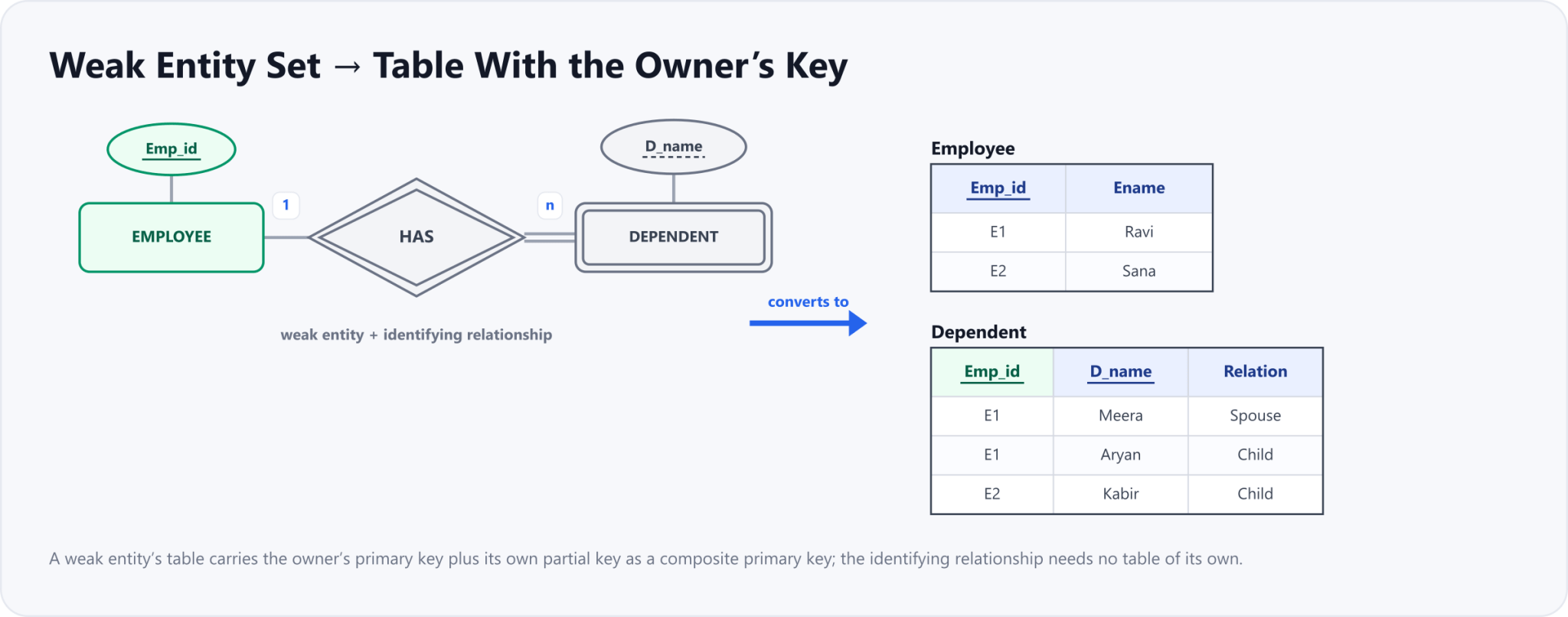
- The Dependent table carries the owner key Emp_id plus its partial key D_name.
- Emp_id and D_name together form the composite primary key.
- The identifying relationship needs no table of its own.
In the example, Dependent is a weak entity owned by Employee. Its table includes Emp_id (borrowed from Employee), the partial key D_name, and any other attributes such as Relation. The composite primary key {Emp_id, D_name} uniquely identifies each dependent, and Emp_id doubles as a foreign key back to Employee. No separate table is made for the identifying relationship HAS.
Quick reference — how many tables?
Here is the whole set of rules on one page. In an exam or an interview, you can often answer "how many tables?" just by scanning the diagram for these cases and adding them up.
| ER construct | Tables | What to do |
|---|---|---|
| Strong entity, simple attributes | 1 | All attributes become columns; the key attribute is the primary key |
| Strong entity, composite attributes | 1 | Use only the leaf (simple) parts as columns; the composite node is not stored |
| Strong entity, multi-valued attribute | 2 | Second table = {primary key, multi-valued attribute}; both together are its primary key |
| Relationship m:n | 3 | Separate relationship table; primary key = both entity keys combined |
| Relationship 1:n or m:1 | 2 | Merge into the "many" side as a foreign key; no separate table |
| Relationship 1:1 | 2 | Foreign key on either side (collapses to 1 table if total participation on both sides) |
| Weak entity set | 1 (+ owner) | Owner’s key + partial key = composite primary key; no table for the identifying relationship |
That completes the reduction rules — you can now take any ER diagram from this series and turn it into a clean relational schema of tables, primary keys, and foreign keys. With the schema in hand, the next step in designing a good database is making sure those tables are free of redundancy, which is what normalization is for.
Drafted with AI assistance from an author outline and edited by TechToolsHQ.