
The big picture: two machines and a network
At the highest level, sending data is simple: it travels down the sender’s stack, across the network, and up the receiver’s stack. The same set of layers exists on both machines, so each layer effectively has a conversation with its counterpart on the other side.

- Machine A wraps the data layer by layer (encapsulation); the receiver unwraps it in reverse (decapsulation).
- The same layers exist on both machines, so each layer talks to its peer.
What is the OSI model?
The OSI (Open Systems Interconnection) model is a reference model that splits networking into seven layers, each with one clear job. Data is handed from one layer to the next, and every layer only needs to understand its own job — that separation is what makes networking manageable.

Application
HTTP, DNS, SMTP - the user's data
Presentation
TLS, encoding, compression
Session
open, manage, and close the conversation
Transport
TCP or UDP, ports, segments
Network
IP addressing and routing, packets
Data Link
MAC framing, frames
Physical
bits on the medium
Encapsulation: what gets added on the way down
As data moves down the sender’s stack, each layer wraps it in that layer’s own header (and the data-link layer adds a trailer too). This wrapping is called encapsulation, and the unit of data gets a new name at each step — its Protocol Data Unit, or PDU.
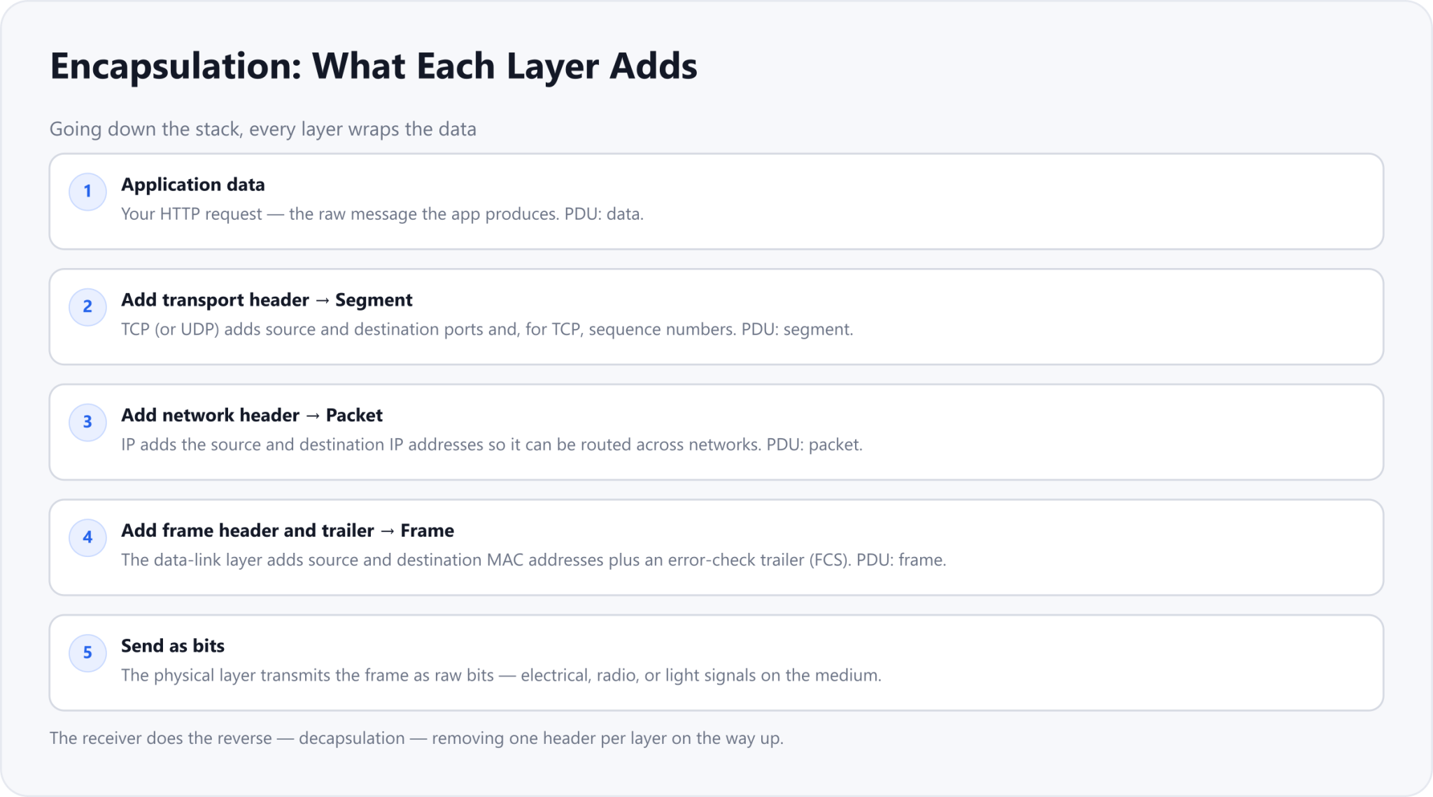
Application data is your HTTP request
Transport adds ports, making a segment
Network adds IP addresses, making a packet
Data link adds MAC and a trailer, making a frame
Physical sends the frame as bits
The result is a set of nested envelopes: the application’s data sits inside a transport segment, inside a network packet, inside a data-link frame. Each header is read by the matching layer on the other machine.
[ Frame   — MAC src/dst + FCS trailer
  [ Packet   — IP src/dst
    [ Segment   — TCP ports + sequence
      [ HTTP data ] ] ] ]
The per-layer summary
Put side by side, here is what each layer is responsible for and what it adds to the data on the way down.
| Layer | PDU | What it adds |
|---|---|---|
| 7 · Application | Data | The message itself (HTTP, DNS, SMTP) |
| 6 · Presentation | Data | Encryption / encoding (e.g. TLS) |
| 5 · Session | Data | Session setup and control |
| 4 · Transport | Segment | Source + destination ports (TCP/UDP) |
| 3 · Network | Packet | Source + destination IP addresses |
| 2 · Data Link | Frame | Source + destination MAC + FCS trailer |
| 1 · Physical | Bits | Nothing — just signals on the medium |
A complete example: an HTTPS request
Say Machine A’s browser (private IP 192.168.1.10) requests a page from Machine B’s web server (13.234.56.78) over HTTPS. Follow the same request down, across, and up. The addresses and ports below are illustrative.
Going down Machine A (encapsulation)
Each layer adds its own information before handing the data to the layer below:
| Layer | Added at Machine A |
|---|---|
| 7 · Application | GET / HTTP/1.1 (Host: example.com) |
| 4 · Transport (TCP) | src port 54321, dst port 443 |
| 3 · Network (IP) | src 192.168.1.10, dst 13.234.56.78 |
| 2 · Data Link | src + dst MAC, plus FCS trailer |
| 1 · Physical | bits over Wi-Fi or Ethernet |
Across the network
Routers forward the packet toward its destination based on the IP header (Layer 3). At each hop, the Layer 2 frame is rebuilt with new source and destination MAC addresses for the next link, while the Layer 3 packet (the IP addresses) stays the same end to end. On the way out of your network, NAT also swaps your private source IP for the router’s public IP.
Going up Machine B (decapsulation)
When the bits arrive at Machine B, the process runs in reverse — decapsulation. The physical layer reads the bits into a frame; the data-link layer checks the trailer and strips the MAC header; the network layer strips the IP header; the transport layer strips the TCP header and hands the ports to the right application; and finally the server’s application receives the original HTTP request, exactly as it was sent.
Where routers and switches fit
This is also why network devices are described by layer. A switch operates at Layer 2 — it forwards frames using MAC addresses on the local network. A router operates at Layer 3 — it forwards packets between networks using IP addresses. When someone says "a layer-3 device," this is the layer they mean.
Drafted with AI assistance and edited by TechToolsHQ.